This is quick excessive developed by myself with the following specific objectives:
- C++ and electronics refresher.
- Learning how to play with Arduino’s for random projects and, why not, for educational purposes.
- Because learning binary is key to have a better understanding of computers.
- Just for fun.
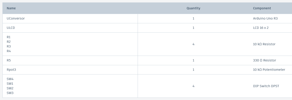
First, let’s start with the materials required.
I used Tinkercad to build and program this project. Here is the electronics diagram.

And here is how it looks like on the simulator.
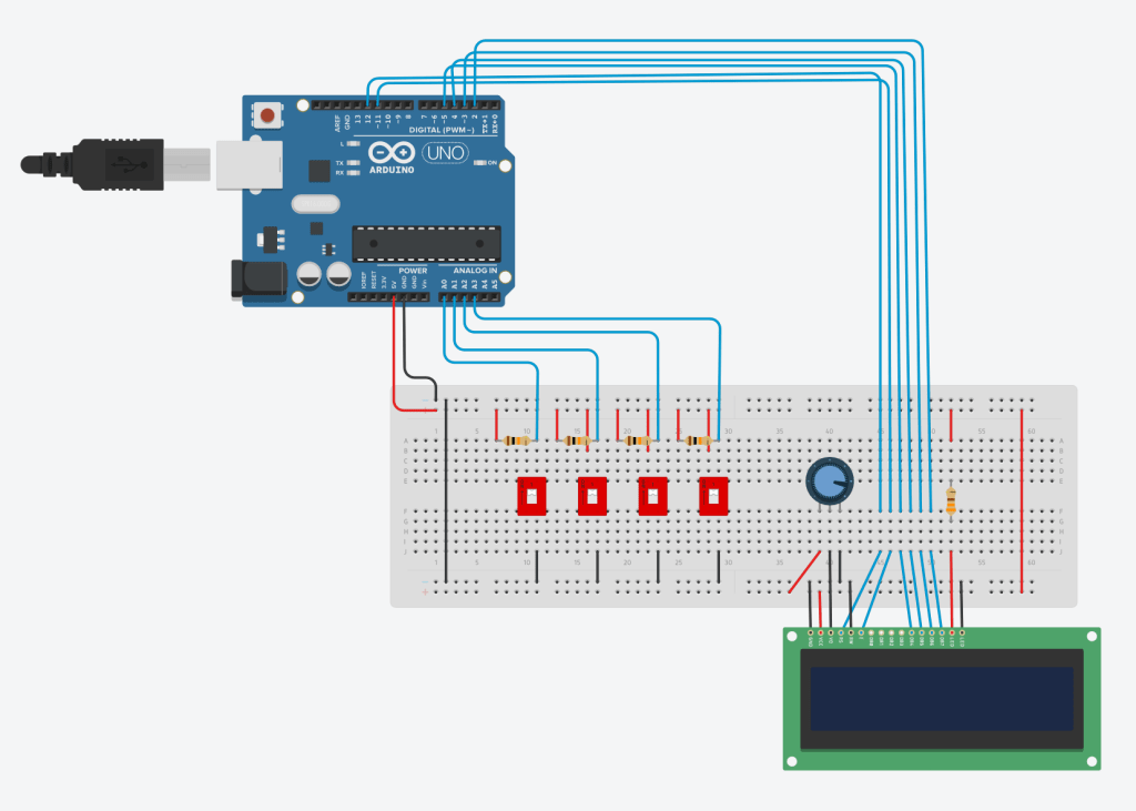
What it does is let the user input a 4 bit binary digit. Being that interrupting the electricity flow represent a one and allowing the flow to go through the analogic inputs on the Arduino is considered a zero.
The resistors value was calculated using the module’s specs. For example, to avoid any current damage, I decided to put a 330 ohms resistor between the 5V power supply flow and the anode port on the LCD. Also, and after checking the LCD module specs, I managed to install a 10k ohms potentiometer to regulate the brightness and resolution of the screen.
Here, the analogic inputs of the Arduino are always getting the 5v signal because all the switches are opened. For today’s example, we will name this state zero. When all the switches are opened, no electricity flows through them and the binary state will be considered as a 0. As soon as a switch is closed, the electricity flow will take the shortest path to the ground. Just like the gravity, the electrons will always be pushed to the ground. However, and only because electrons require certain materials that will ease the flow to the ground, the 5v signal will no longer be pushed to the analogic inputs on the Arduino until the switches are opened back again. In the meantime, the electrons will follow the path through the switches in order to reach the ground. This will be called the state 1. Being that, the lack of the 5v signal will input a 0 on the bit that happens to have the switch closed.
This is how we can have us the switches as buttons to input a 4 bit binary number that will then be converted to decimal notation. To finally be printed on the default LCD module as instructed using C++.
Feel free to find the code to make it happen here:
https://www.tinkercad.com/things/cLzLWTBlEAs
#include <LiquidCrystal.h>

const int numInputs = 4; // Number of binary inputs
const int analogPins[numInputs] = {A0, A1, A2, A3}; // Analog input pins for the switches
int binaryInputs[numInputs]; // Array to store the binary inputs

LiquidCrystal lcd(12, 11, 5, 4, 3, 2); // LCD RS, RW, EN, D4, D5, D6, D7

void setup() {
  lcd.begin(16, 2); // Initialize the LCD display
  lcd.print("Decimal Value:");
}

void readBinaryInputs() {
  for (int i = 0; i < numInputs; i++) {
    binaryInputs[i] = analogRead(analogPins[i]) > 512 ? 1 : 0;
  }
}

int binaryToDecimal() {
  int decimalValue = 0;
  for (int i = 0; i < numInputs; i++) {
    decimalValue |= (binaryInputs[i] << (numInputs - 1 - i));
  }
  return decimalValue;
}

void displayDecimalOnLCD(int value) {
  lcd.setCursor(0, 1);
  lcd.print("              "); // Clear previous value
  lcd.setCursor(0, 1);
  lcd.print(value);
}

void loop() {
  // Read binary inputs
  readBinaryInputs();

  // Convert binary to decimal
  int decimalValue = binaryToDecimal();

  // Display the result on the LCD
  displayDecimalOnLCD(decimalValue);

  delay(100); // Add a small delay for stable display
}
Feel free to share your comments, thoughts, concerns, and even feedback if you wish to do so.
By the way, here are the links to buy some of the gear required:
Arduino. https://amzn.to/3OLNN1w
Push and lock switches. https://amzn.to/3Ymdb19
Proto-board: https://amzn.to/3Yvqcpe
Thanks for your time, and I will catch you all later.
